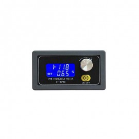
ماژول PWM ژنراتور تک کاناله روپنلی XY-KPWM
- برد رزبری پای - RASPBERRY PI
- بردهای کاربردی تحت سیستم عامل
- بردهای کاربردی صنعتی
- تجهیزات الکترونیک
- تجهیزات جانبی
- تغذیه سوئیچینگ صنعتی-آداپتور-منبع تغذیه
- جعبه - کیس های مدار و برد
- دستگاه کنترل پیامک
- ماژول ها
- ISM Band
- LCD
- درایور موتور
- دوربین
- ماژول اثر انگشت
- ماژول دما و رطوبت
- ماژول سنسور گاز
- ماژول های GSM/GPS/GPRS
- ماژول های RFID
- ماژول های آلتراسونیک
- ماژول های بلوتوث
- ماژول های تایمر و پالس
- ماژول های تغذیه و ولتاژ
- ماژول های شبکه و WIFI
- ماژول های شتاب سنج و ژیروسکوپ
- ماژول های صوتی و آمپلی فایر
- ماژول های فرستنده و گیرنده
- ماژول های فشار
- ماژول های مبدل
- ماژول های پزشکی و ضربان قلب
- ماژول های کاربردی
- ماژول پرینتر
- موتورها
- پروگرامرها
- کتاب های آموزشی و کاربردی
- کیت های آموزشی
- بردهای آموزشی ARM , AVR , PIC , FPGA
- روباتیک
- آردوینو
- سنسورها
- LED
- ریموت و کنترل کننده های صنعتی و کاربردی
- آنتن ها
- قطعات پروازی و ربات های پرنده
سبد خرید شما خالی است !
توضیحات محصول
ماژول PWM ژنراتور تک کاناله روپنلی XY-KPWM
اندازه ابعاد 78x42x26mm
ولتاژ
کاری 3.3 تا 30 ولت با دقت 0.1 درصد دیوتی سایکل(زمان وظیفه) و تنظیم بوسیله ولوم
انکودر با خطای فرکانسی 2% و جریان سیگنال خروجی 5 تا 30 میلی آمپر و دامنه خروجی،
برابر با ولتاژ ورودی می باشد.
رنج
فرکانس کاری وسیع، در دو مد Normal و
fine (مد fine برای کاربردهای
با دقت بالا و فرکانس های پایین استفاده می شود) و پشتیبانی از ارتباط سریال UART برای برنامه
ریزی و تنظیم پارامتر با بادریت 9600 و طول داده 8 بیتی و 1 بیت پایان.
محدوده فرکانسی
در مد
Normal: یک هرتز الی 150KHz (با
دقت 1 درصد)
در مد
fine: یک هرتز الی 15KHz (با
دقت 0.1 درصد)
برای
تغییر مد ولوم را به مدت 5 ثانیه فشار می دهیم
محدوده فرکانس خروجی
XXX دارای
دقت 1Hz می باشد از 1 تا 999 هرتز (100 >>>
100Hz)
X.XX دارای
دقت 0.01KHz از 1 تا 99.9 کیلوهرتز (1.01 >>>
1.01KHz)
XX.X دارای
دقت 0.1KHz از 10 تا 99.9 کیلوهرتز (54.1 >>>
54.1KHz)
X.X.X دارای
دقت 1KHz از 1 تا 150 کیلوهرتز (1.2.4<<<124KHz)
تنظیم پارامترها
برای
تعیین پارامترهای فرکانس و دیوتی سایکل با فشار دادن لحظه ای ولوم وارد تنظیمات
فرکانس می شویم و با زدن دوباره آن دیوتی سایکل قابل تنظیم است. با مشاهده
Set پارامتر آماده تنظیم شدن است. در نهایت با حذف شدن
علامت چشمک زن تنظیمات پایدار شده و خروجی با توجه به پارامترهای تنظیم شده
موج مربعی را تولید می کند. با مشاهده out شکل موج مربعی
پایدار در خروجی حاصل شده است. اگر ولوم را به مدت 3 ثانیه نگه داریم به تنظیمات
محدوده دیوتی سایکل دسترسی خواهیم داشت که حد بالا و پایین دیوتی سایکل را مشخص می
کند.
Introduction
XY-KPWM signal generator is a device that provides electrical
signals at a variety of frequencies, square wave, and output levels.It is used
as a signal source or excitation source for testing.Widely used in production
practice and technology.
Feature
1>.With outer casing
2>.LCD high definition display
3>.Support UART
4>.Support frequency adjustment
5>.Support duty cycle adjustment
6>.High precision detection
7>.Support power-down memory function
8>.1-Channel PWM output
9>.Dual Work Mode
10>.Knob supports lock function to avoid misoperation
11>.Support enable output
Specification
1>.Product name: XY-KPWM PWM Signal Generator;
2>.Model: XY-KPWM;
3>.Work Voltage:DC 3.3V-30V;
4>.Frequency range(Normal mode):1Hz~150KHz;
5>.Frequency range(Precise mode):1Hz~15KHz;
6>.Frequency accuracy:2%;
7>.Duty cycle accuracy:1% at Normal mode;
8>.Duty cycle accuracy:0.1% at Precise mode;
9>.Duty cycle range:0.00%-100%;
10>.Output Current:About 5-30mA;
11>.Output amplitude:Same to input voltage;
12>.Work Temperature:-40℃~85℃;
13>.Work Humidity:0%~95%RH;
14>.Size:79*43*37mm;


